Terminal configuration
Designed for storing and handling liquid bulk in the Fujairah Oil Industry Zone, and configured for conventional petroleum products.
In brief
200,000 m²
SITE AREA
33
TANK COUNT
50
YEAR LAND LEASE
25 + 25 YEARS
≈1.2M m³
CAPACITY
Liquid bulk
Storage & handling
Clean and black
Product segregation
Blending
Circulation
Site and setting
Project overview
Strategic Location
The plot lies within the Fujairah Oil Industry Zone (FOIZ), counted among the world’s key hubs for energy trading and storage.
Prime Plot Under Lease
A 25 + 25-year lease with FOIZ secures roughly 200,000 sq. metres of land.
Rare & Strategic Site
The plot APEX has secured is stated to be the last one in FOIZ available for a new terminal.
Future-Ready Infrastructure
Designed for handling conventional hydrocarbons as well as emerging products, SAF and biofuels among them.
Tank farm functions
Product legend
- BPP · BLACK PETROLEUM PRODUCTS
- CPP · CLEAN PETROLEUM PRODUCTS
- SLOP · SLOP TANKS
- CPP/BPP · DUAL-SERVICE
Tank Farm 1
BLACK PETROLEUM PRODUCTS
366,436 m³ · 6 TANKS
- 4 BPP × 84,823 = 339,292
- 2 tanks × 13,572 = 27,144
Tank Farm 2
CLEAN · DUAL-SERVICE · SLOP
577,532 m³ · 14 TANKS
- 10 CPP × 47,713 = 477,130
- 2 CPP/BPP × 47,713 = 95,426
- 2 slop × 2,488 = 4,976
Tank Farm 3
CLEAN PETROLEUM PRODUCTS
275,678 m³ · 13 TANKS
- 13 CPP × 21,206 = 275,678
Capacity by product
1,219,646 m³
31 storage tanks · 2 slop tanks
The tank register gives the exact split across Tank Farms 1 to 3.
Pump sets and pipelines
BPP pump sets
- 4 × positive-displacement
- 5,000 m³/h per unit
- 750 m³/h stripping pump
CPP pump sets
- 4 × centrifugal
- 2,500 m³/h per unit
- 500 m³/h stripping pump
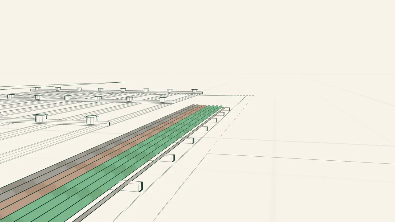
Line sets by product
Black products
For crude oil and fuel oil
Middle distillates
For clean products
Light distillates
For clean products
Slop and flexible service
Under the approved operating basis
Pipeline arrangement
Line sets split by product, taken from the current internal technical basis.
Subject to approved routing and detailed engineering.
8
PRODUCT-TRANSFER LINES
1
NITROGEN UTILITY LINE
4
INDEPENDENT LINE SETS

Line count × diameter
2 × 36″
Crude oil
2 × 30″
Fuel oil
4 × 24″
White oil / CPP
1 × 8″
Nitrogen utility
- MM2 tie-in
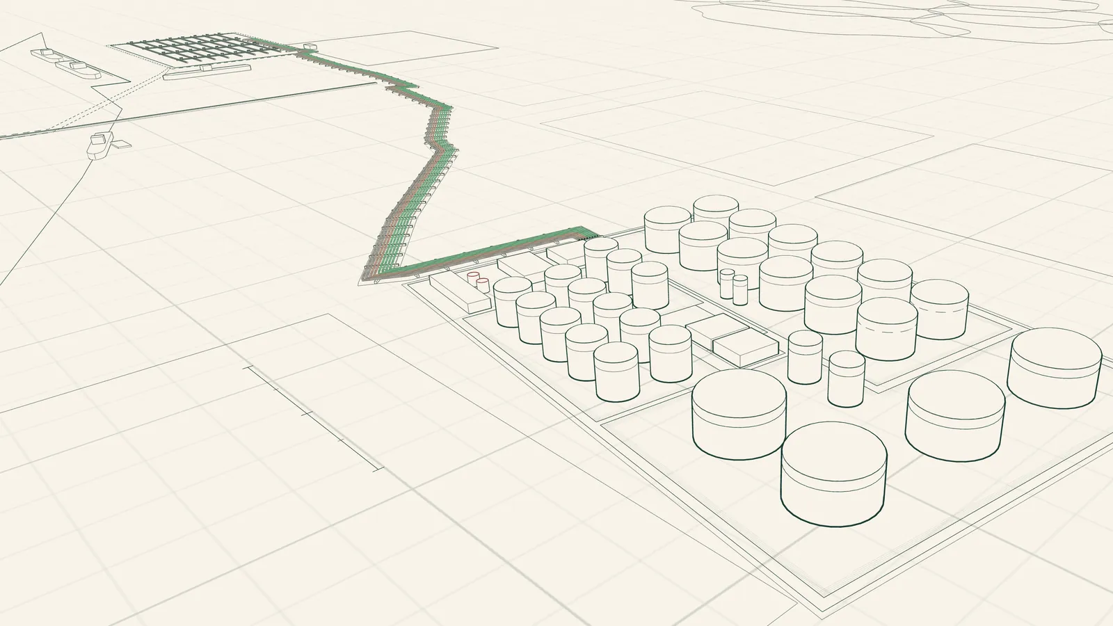
Corridor to MM2
The source plan shows the corridor leaving Apex Terminal at Start Point A1 and reaching POF MM2 at End Point B1.
A1
APEX TERMINAL · START OF ROUTE
B1
POF MM2 · END OF ROUTE